
Bearing Mandrel: Technical Specifications, Manufacturing Process and Industrial Applications
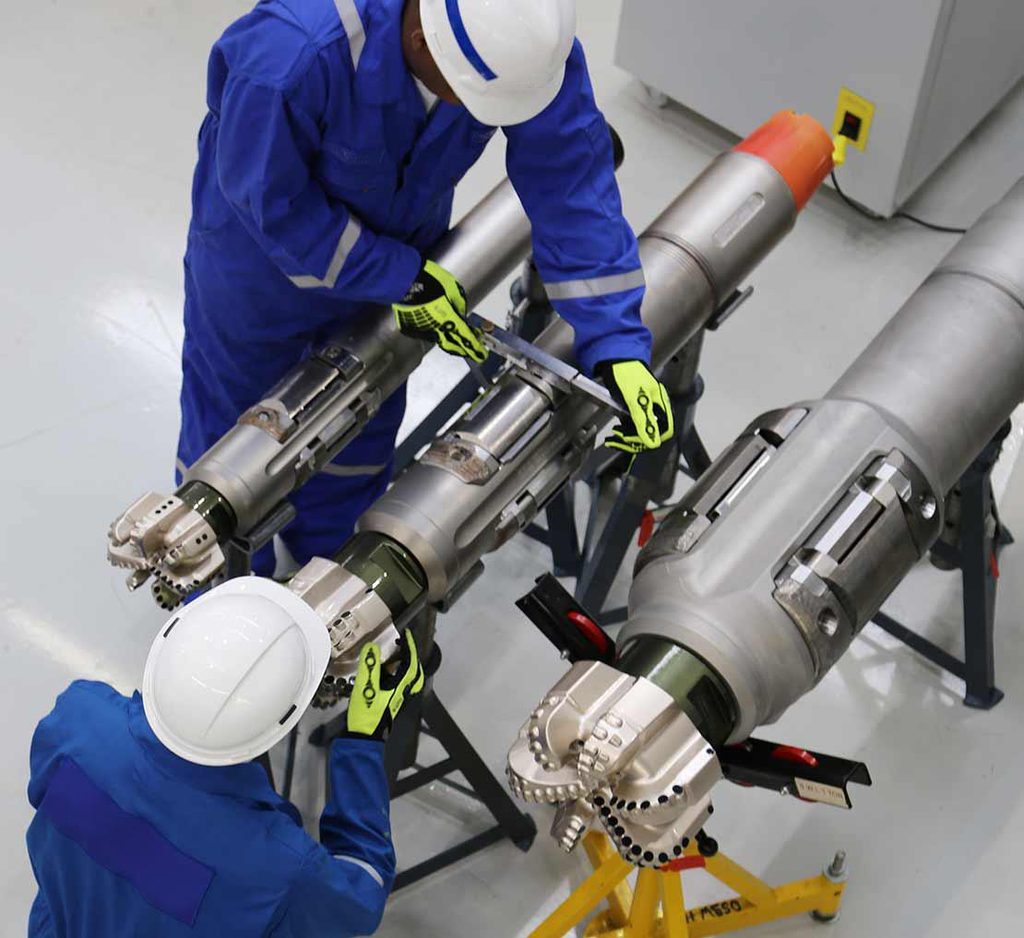
Bearing Mandrel: Technical Specifications, Manufacturing Process and Industrial Applications
1. What Is a Bearing Mandrel?
A Bearing Mandrel is a precision-machined mechanical component designed to support, position, locate or guide rotating components within mechanical assemblies. It typically features a stepped shaft structure with multiple precision-machined diameters, bearing mounting surfaces, locating shoulders, grooves and, in some designs, an internal bore.
Bearing mandrels are designed according to the mechanical structure and operating requirements of the equipment in which they are installed. Depending on the application, they may need to withstand radial loads, axial forces, rotational movement, friction and demanding operating environments.
Changzhou Oulin Machinery Manufacturing Co., Ltd. provides custom precision-machined components based on customer drawings, technical specifications and application requirements. Our machining capabilities include CNC turning, milling, multi-axis machining and EDM processing.
2. Bearing Mandrel Structure and Technical Specifications
The component shown in this article features a stepped cylindrical structure with several functional machining areas:
- Bearing Mounting Surface: Provides a precision mounting interface for bearing installation.
- Stepped Shaft Sections: Different shaft diameters meet assembly and positioning requirements.
- Locating Shoulders: Control the axial positioning of bearings and other mechanical components.
- Retaining Grooves: May accommodate retaining rings or other positioning components, depending on the design.
- Central Bore: Provides an internal passage or meets weight and structural requirements, depending on the application.
- Precision End Sections: Provide connection, positioning or assembly interfaces.
Main Technical Parameter
| Parameter | Technical Requirements |
| Product Name | Bearing Mandrel |
| Component Type | Stepped Hollow Shaft |
| Manufacturing Methods | CNC Turning, Milling, Grinding and EDM, as required |
| Material | Alloy Steel, Carbon Steel, Stainless Steel or customer-specified material |
| Outer Diameter / Inner Diameter | Customized according to drawings |
| Overall Length | Customized according to drawings |
| Bearing Fit Diameter | Specified according to bearing and assembly requirements |
| Dimensional Tolerance | According to engineering drawings |
| Surface Roughness | According to functional surface requirements |
| Hardness | Determined by material and heat-treatment requirements |
| Heat Treatment | Quenching, tempering or other specified treatment |
| Surface Treatment | According to customer requirements |
| Inspection | Dimensional inspection and CMM measurement, as applicable |
Engineering note: There is no single universal dimensional or tolerance standard for all bearing mandrels. Actual dimensions, fits, surface roughness and hardness must be confirmed against the customer’s drawings and operating conditions.
3. Material Selection for Bearing Mandrels
3.1 Alloy Steel
Alloy steel is a common option for mandrels subjected to mechanical loads and demanding working conditions. Potential benefits include good mechanical strength, fatigue resistance and heat-treatment capability. Material options may include 4140, 42CrMo and equivalent grades, subject to engineering requirements.
3.2 Carbon Steel
Carbon steel may be considered where mechanical loads and wear requirements are moderate. It offers cost-effective material options and good machinability in suitable grades and conditions.
3.3 Stainless Steel
Stainless steel may be selected when corrosion resistance is important. The specific grade should be chosen according to the chemical environment and mechanical requirements.
3.4 Material Selection Considerations
- Working load and torque
- Operating speed and temperature
- Corrosion exposure
- Wear and friction conditions
- Required hardness and expected service life
Material selection should be based on the actual equipment application rather than price alone.
4. Manufacturing Process of a Precision Bearing Mandrel
Step 1: Engineering Drawing Review
Review 2D drawings, 3D models, overall dimensions, shaft diameters, bearing fits, bore dimensions, geometric tolerances, surface roughness, material and heat-treatment requirements. Identify potential manufacturing issues before production.
Step 2: Raw Material Preparation
Prepare material according to the engineering requirements. Material grade, dimensions and traceability can be checked according to customer requirements.
Step 3: CNC Turning
Machine external cylinders, internal bores, stepped diameters, shoulders, grooves, end faces and chamfers. Turning establishes the basic geometry and functional surfaces.
Step 4: Milling and Secondary Machining
Perform keyway, flat, slot or other special-feature machining where required. Multi-axis machining may be used for more complex geometries.
Step 5: Heat Treatment
Apply quenching and tempering, induction hardening, surface hardening or another specified process when required by the drawing. Parameters depend on material, hardness and service conditions.
Step 6: Precision Grinding and Finishing
Grind critical bearing mounting surfaces and functional diameters when required to achieve dimensional accuracy, surface finish, roundness and cylindricity.
Step 7: EDM Machining
Use EDM for selected geometrical features that are difficult to produce by conventional cutting, depending on geometry, material and technical requirements.
Step 8: Final Inspection and Quality Control
Verify critical dimensions, diameters, shoulder positions, grooves, geometric tolerances, surface roughness and hardness where specified. CMM inspection can support complex dimensional and geometrical measurement.
The actual operation sequence may vary. For example, some precision surfaces may require grinding after heat treatment. The process route should be determined by the material, geometry, tolerance requirements and production method.
5. Industrial Applications of Bearing Mandrels
Oilfield Equipment
Bearing mandrels may be incorporated into certain oilfield mechanical assemblies, downhole equipment and drilling-related systems where precision positioning and reliable mechanical interfaces are required. Suitability must be evaluated against actual operating conditions.
Drilling Equipment
Certain drilling equipment assemblies use precision-machined shaft components to support rotating elements and maintain mechanical alignment. Custom mandrels can be manufactured according to equipment-specific drawings.
Industrial Machinery
Potential applications include rotating assemblies, transmission systems and specialized industrial machinery.
Custom Mechanical Assemblies
For non-standard machinery, mandrels can be manufactured to customer-specific dimensions, mounting interfaces, material grades and surface-treatment requirements.
6. Common Manufacturing Challenges
Coaxiality Control: Multiple stepped diameters may need to maintain a specified coaxial relationship for assembly and rotational performance.
Bearing Fit Accuracy: Bearing mounting surfaces must meet specified dimensional and geometric requirements. Incorrect fits can cause assembly difficulties or unwanted clearance/interference.
Surface Quality: Surface roughness at bearing mounting areas can affect assembly, friction and wear.
Heat-Treatment Deformation: Heat treatment can cause dimensional changes or deformation. Machining allowances and subsequent finishing should be considered.
Complex Internal Features: Hollow structures and internal features may require specialized tooling and machining strategies.
7. Why Choose Changzhou Oulin Machinery Manufacturing Co., Ltd.?
Changzhou Oulin Machinery Manufacturing Co., Ltd. is a precision machining manufacturer based in Changzhou, Jiangsu, China. We focus on custom-machined components, oilfield equipment parts, hard alloy components and non-standard mechanical parts.
- 5 CNC turning machines
- 2 machining centers, including 1 five-axis machining center
- 4 EDM machines
- 5 fast wire-cut EDM machines
- Coordinate Measuring Machine (CMM) inspection equipment
Our services include custom machining based on 2D drawings and 3D models, material and process evaluation, precision dimensional inspection, and prototype or batch production. Actual process availability and inspection scope are confirmed for each project.
8. Custom Bearing Mandrel Manufacturing Services
Are you looking for a manufacturer of custom bearing mandrels? We can review your requirements based on:
- 2D engineering drawings or 3D CAD models
- Material specifications
- Required quantities
- Dimensional and geometric tolerances
- Surface finish and heat-treatment requirements
- Intended working conditions
Our team can review the component structure and evaluate an appropriate manufacturing process. Whether you require prototype development, replacement parts or batch manufacturing, we welcome your technical inquiry.
SEND US YOUR DRAWINGS TO REQUEST A QUOTE
Contact Changzhou Oulin Machinery Manufacturing Co., Ltd. for precision machining solutions tailored to your requirements.